
Pillarama
Members
-
Joined
-
Last visited
Everything posted by Pillarama
-
I spent some time looking before I got impatient and decided to just do my best soldering job on the factory loom (de-pinned, stripped and wound, then heat-shrinked so it's essentially reversible with just a small break in the original wire casing and no nasty scotch locks). I'm pretty sure this is the correct Aux plug if you decided to just buy one new (but you'll need a crimping tool to assemble it): https://www.aliexpress.com/item/4000181143484.html That listing has the plug and socket so that opens a few different options. I find looking for pre-made looms yields almost exclusively the 6-pin type, rather than the 8-pin variation that my head unit seems to have (RobPearson is yours actually 10 pin? - wow different again...) This one is probably the closest I could find and looks similar enough to the 8 pin that I think it night be possible to make it fit: https://vi.aliexpress.com/item/1005004806076482.html
-
tl;dr So it was late last night (or should I say this morning) when I was working on this and maybe I should have already packed it in for the night. Apparently I must have probed the wrong pins or something (but then weirdly the DMM was definitely responding to button presses so just not how I expected...so IDK), I just double-checked and now it's behaving like I would have expected .... SWG is not measuring 12v to Vehicle ground now and neither is SW1 or SW2 measuring 10.3v as they were either (that is with the plug disconnected from the head unit in any case). And the resistance between SWG and SW1 / SW2 is reading nice consistent, sensible resistance measurements for each button now.... so I think I can make this work... Probably the only thing I'm concerned about is trying to keep the ADC ground separate from the vehicle ground. Since I presume that Toyota did that for good reason....
-
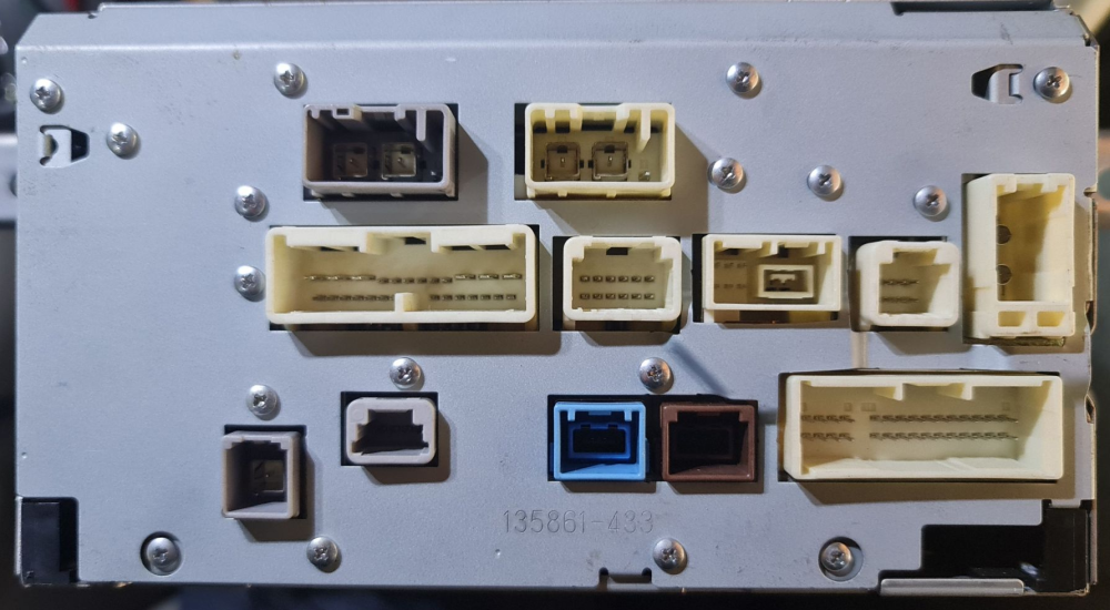
Hi All, I have this head unit: Which I think is identical to the one Chris.ac has. I'm hoping to do multiple upgrades/mods in stages as I have the time but none of my plans involve replacing the headunit itself. The first upgrade I am doing is adding a separate OpenAuto Pro install with Raspberry Pi and a separate Lilliput 7" Screen and send audio to the Aux input - thanks for the info here which described the AV (VTR) input pin-out as that was exactly what I needed there and saved me tracing it. That upgrade is coming along nicely just waiting on my CarPiHat to arrive from UK to complete it. What I want to do now is integrate the steering wheel controls using an intermediate micro-controller between steering wheel and factory head-unit to allow me to "borrow" the steering wheel buttons by having two different "modes" that they can function in (eg press and hold the Mode button (or it that doesn't work, just a new purpose speciifc mode switch somewhere on the dash) and the micro-controller detects that at which point a relay would disconnect the steering wheel wires to the head unit allowing the buttons to then control OpenAuto Pro. Same process then reverses the state to return control to the Head Unit. I have experience with "one wire" resistor-network steering wheel controls from multiple previous vehicles where that one wire essentially goes through a different resistor value to vehicle ground for each button but this three-wire setup is throwing me a bit (More the "SWG" bit than the fact there are SW1 and SW2 which I see is just two groups of buttons). I have tested and can confirm that the two SW1 / SW2 wires (D25, D24) definitely correspond to the left / right groups of buttons as the voltage potential changes as the buttons are pressed (although surprisingly up to to 12v for any button) but the SWG "Switch Ground?" (D23) measures 12v potential difference to vehicle ground and the other two (24,25) measure about 10.3v.....? I didn't expect that... I don't understand what the SWG wire is for... In the past I would have used a pull-up resistor to form varying voltage dividers through the buttons and measure the voltage using an ADC. Does this style work similarly - I'm confused by the SWG being 12v I don't want to risk doing any damage. Also I would have expected the SW1 and SW2 to be 0v if they were just resistor networks to vehicle ground. Does anyone know if I can wire this up similarly so that I can use a pair of ADCs on the micro-controller to read these two sets of buttons? Hoping this isn't some new-fangled digital system? Eventually I thought it would be neat to see if I can hijack the factory interfaces (eg maybe the Parking Assist ECU interconnect) to integrate OpenAuto Pro into the factory head unit similar to what I did with the Sony XAV SatNav add-on connector on my old XAV-601BT which carried RGB / Audio and UART touch info etc... or alternatively reverse engineer the factory head unit Firmware to see if any useful modifications can be made in software (eg translation to English / replacement of the satnav software / hiding the GBook stuff etc). But those projects are for another year.... Any assistance / insight would be greatly appreciated! Chris.ac is there any way you might be able to direct/assist me somehow on acquiring a full copy of the wiring diagrams that you have? Thanks