
dph
Members
-
Joined
-
Last visited
-
I don't think the seller gave me the auction sheet - but i can see from the MoT history that the recorded odometer figure for the first MoT done in July 22 was the same figure as is being displayed now, despite driving a couple of thousand miles over the last 2 months. The seller has gone very quiet since emailing to say I wanted to discuss the car. It's an 'appointments only' type place that is advertised on Autotrader, and has several similar vehicles for sale.
-
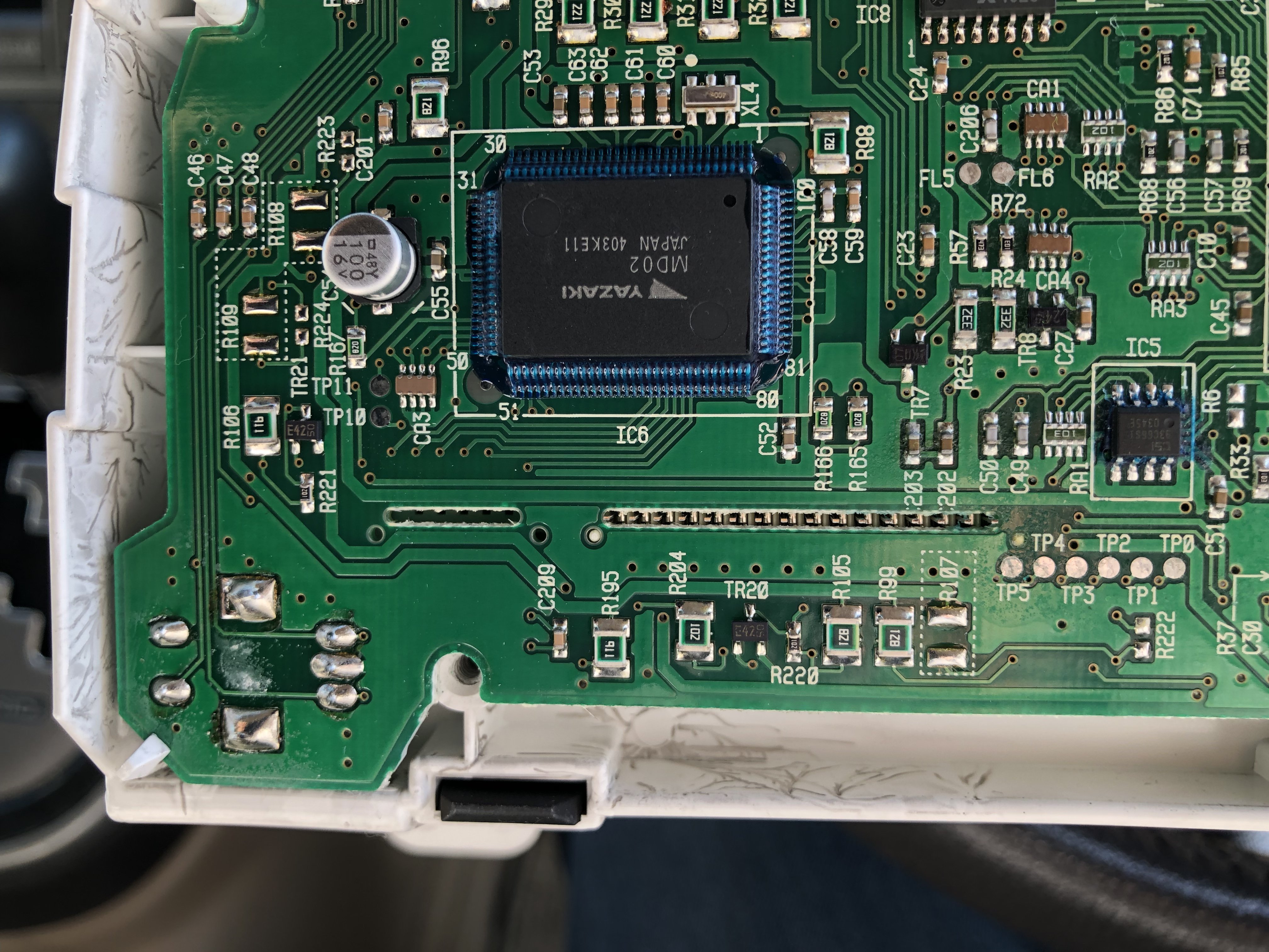
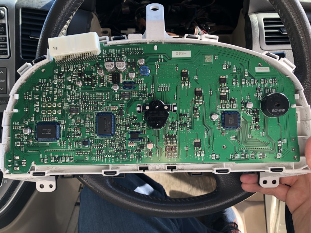
Further update. So I decided to buy another km/h to mph converter ( well 2 actually, one they looked similar to the one that was in there, and a different looking one) mainly so that I knew I had a new device / chip or resistor or whatever is in them and secondly so that I had some advice / diagrams on how to wire them in. If anyone has a detailed circuit diagram for the speedo cluster I’d be greatful as I ended up having to work out what was need by guesswork and some reference to the instructions that came with the converters. so I have a functioning speedo again, soldered in, which is indicating speed in mph, but the odometer is still not working. I decide to take the back off the speedo cluster to have a look at the circuit board. I felt sure someone had been in here before because there was a screw missing and various screwdriver type scrape marks. And my odometer is showing 5 figures eg 61,223 miles or Kim’s ( not sure) whereas I expected it to show 061,223 ?? I don’t know if this is a fair assumption as I don’t have anything else to compare it with. Anyhow, I attach a pic of the back of the board … if anyone else has a similar pic it would be useful to see to compare. My attention was drawn to the bottom left corner which is where the odometer display is… resistor R107 and resistor R222 might be missing on mounted on the other side of the board? again, any suggestions gratefully received. I want to get to the bottom of this and get the odometer working again.

-
Thank you I wasn’t sure how to message him privately
-
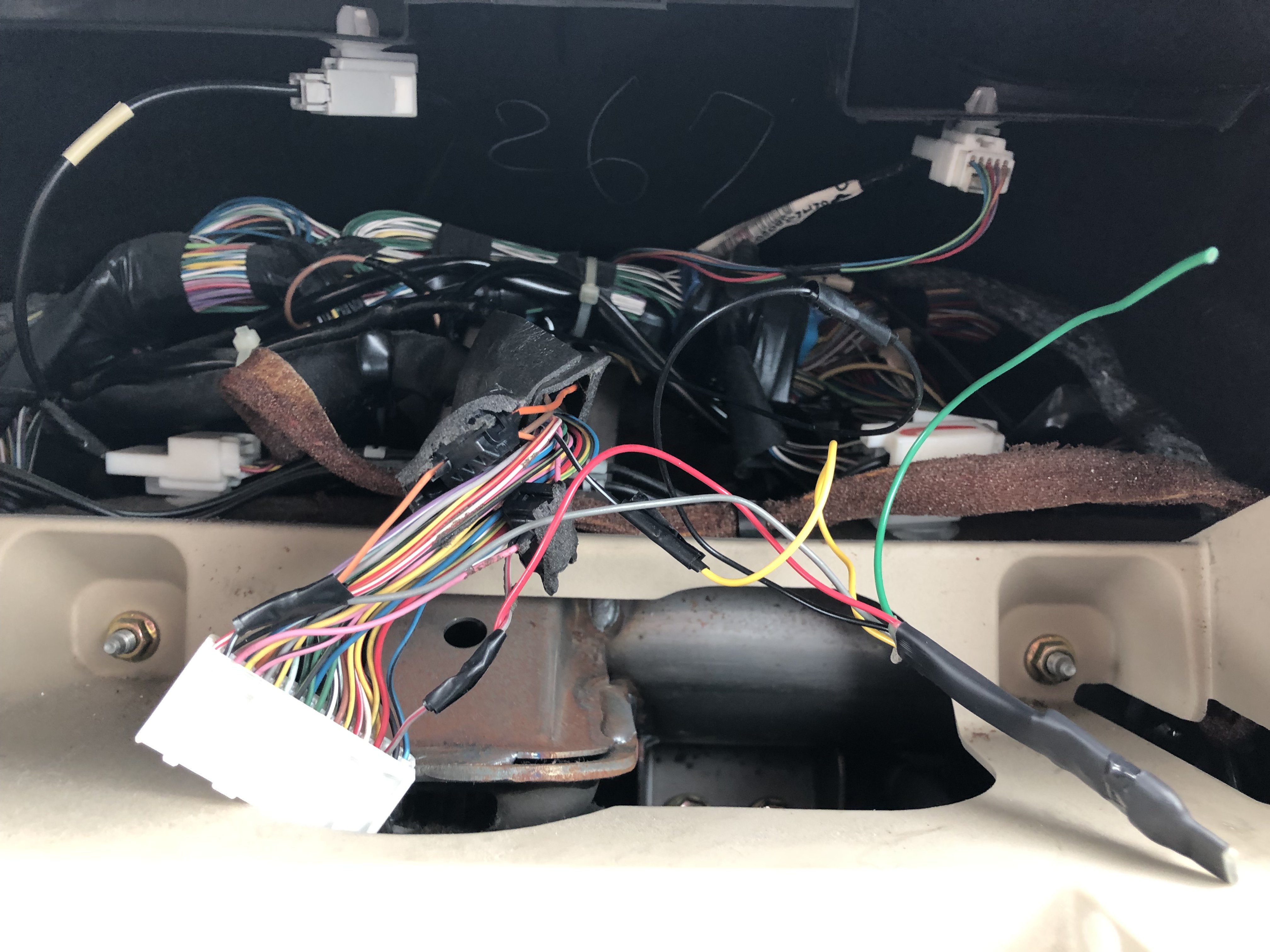
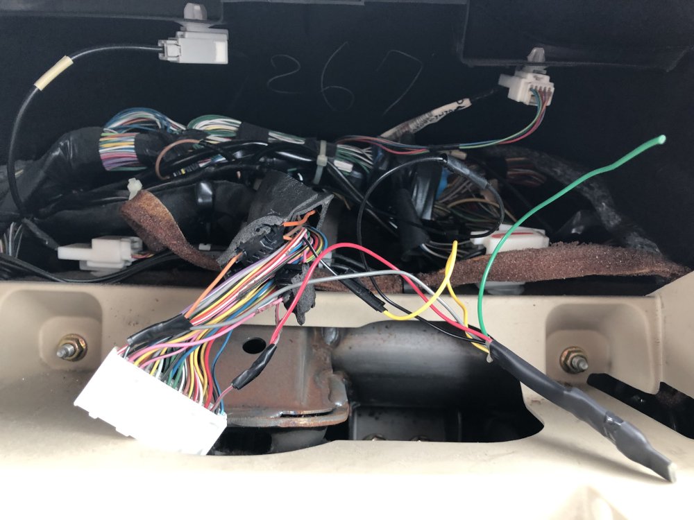
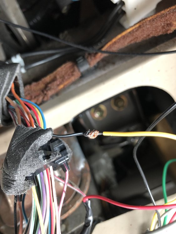
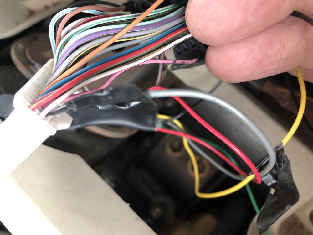
Thanks that would be very helpful. You can send any info to (DELETED). attached are a couple of photos of what was back there. Not that pretty.
-
hi there, bought an alphard while overseas (I know I know what was I thinking)... had to ... family arrived back in UK before me. Anyhow, drove it for a while 2000 miles or so, tapped the trip meter (which works) and notice that the odometer reading has not changed at all. Pulled the instrument cluster out to have a look. Found a km to miles adapter thing. Not soldered in.... wires wound around each other and taped.... removed that, to see if putting it back to standard helped. Result was speedo now reads in kms not miles (to be expected) but odometer still not working. Tried to identify if there was some kind of other device there... a 'mileage blocker' that I've seen advertised... don't think there is. Any idea how to address the non-working odometer. Anything to look for on the board of the speedo itself? haven't opened that up yet. Thanks