
Jeza
Members
-
Joined
-
Last visited
Everything posted by Jeza
-
Are you sure it is P1325 as inverter faults are P3123-xxx, if so, you need to find the sub code (-xxx) to identify the part in the inverter or wiring to the ECU's.
-
Because of its small capacity of 44Ah, it is important to keep it charged up if not regularly using the vehicle, at least once a week. I plug in the AC hook up every week ,with a dehumidifier running inside as well when not using the van after the roads have been gritted or a foot of snow as we have now.
-
Check with your conversion company to see what battery they installed. It has to be low enough to clear the underside of the seat, I guess it is raised up slightly with a swivel base. If it is a CampervanCo conversion they installed a Red top AGM battery in mine.

-
You don't need to power down the HV to clean the Hybrid ECU. From the description of what is happening and the lights it looks like a HV battery issue, one bad block is all it takes. If the capacity of the block reduces, it will charge up quicker then discharges quicker than the rest. You also have a HV battery temp warning on and a motor generator temp warning on as well, is the HV battery cooling fan on max. Check behind the front passenger seat forward trim in the footwell for water, the HV battery ECU connector is there. You need to get a code reader to find out what is going on.
-
Finger trouble!! just replace the bad pair of cells. A few hybrid battery repair companies around that can test and repair your battery.
-
Hi, I presume it is, a better performing with smarter charging than the gen 2. You have to replace all the modules within the battery. The battery is only as good as the weakest cell, so you could
-
A power seat mechanism and side lift-up mechanism are available on the left side of the captain's seat as a manufacturer option. Approx dimensions; Ground to floor - 52cm Rear door lower opening trim to top of rear opening - 120cm As Rojie has already mentioned the tail gate hangs down a bit when open

-
If you are removing the engine ECU to clean the contacts and harness connectors, the hybrid ECU is the box forward and at right angles to it. While you are in there, it would be worth cleaning those contacts /connectors as well.
-
They are on facebook which gives you some idea of the different work they do plus reviews.
-
Try AME vehicle service & repair - Insch aberdeenshire. I use them for my 2003 hybrid great service, I am about to get them to change the rear trailing arm bushes, I usually provide the parts.
-
If the 12v battery, most likely the engine ECU relearning the idle settings after battery disconnection. Also you will find the drivers door window controls for the other doors won't work, you need to lower and raise each window by its own door switch first.
-
Initial engine start by turning the key uses the Hybrid motor in the gearbox. Subsequent engine starts uses the starter/generator driving the toothed serpentine belt on the front of the engine. Check the belt first, also the tensioner, water pump, aircon pump, idler pulley and crankshaft pulley which are all connected to the belt.
-
I have an ICarsoft reader for the early toyota, 2003 hybrid, and techstream. Techstream gives far more info and is easier to read live data. However I find if the Hybrid system has gone into safe mode, or worse, neither can communicate with the ECU. The early models communicate through the OBD port on the J line to the engine ECU, the canbus is very limited.
-
C1213 - The skid control computer communicates with the hybrid control computer and controls the braking force in coordination with the motor regenerative operation. Reception or transmission to or from the hybrid control computer is not possible. Check the sub code on the data page, could be 152, 153 or 154. This is not necessary a fault, if there is an issue with the hybrid system it stops talking to the other systems. P1636/81 When communication from the Engine Control Computer with the hybrid vehicle control computer is lost Possible issues - Wire Harness or Connector or computers P3002 - When an error occurs in communication from the hybrid vehicle computer to the battery computer ASSY Wire Harness or Connector Hybrid Vehicle Computer Battery computer assembly As the hybrid computer seems to be the common issue I would check all the connectors and harnesses on both the ECU, hybrid computer and battery ECU for damage and water ingress. ECU's are located behind the passenger stowage box and the battery ECU under the passenger seat, connector accessible behind forward trim. I can give you the connectors and relevant pins to check for continuity of each harness. Interestingly on P3002 fault diagnosis the first check is to "Stop operation of all aftermarket vehicle products or electrical products brought into the vehicle." then check if the fault code reappears. attached images are for P3002.


-
If the light comes on, when you stop check for codes before turning the engine off.
-
The inverter/converter is very well sealed as is the battery. I would look at this as two separate issues to start with. Do you get any warning lights come on? Is the 12v aux battery good, full capacity and holding charge? When trying to start can you hear the Hybrid relays click from under the passenger seat? Have you checked for any jobd fault codes? Low power could be the engine or the Hybrid system sensing an issue and going into safe or limp mode, engine revs more especially at low speeds. I presume the water leak clear water and not coolant!
-
Knock sensor P0325/52 - When the knock control sensor is disconnected or shorted for 10 seconds or more at an engine speed of 2000 to 4500 rpm after the engine has warmed up. Possible issues; Wire Harness or Connector - ECU connector B, kah11476 pin 20 Knock Control Sensor - this is hidden under the inlet manifold, I read somewhere that it is possible to access it from going in from under the engine!! Knock control sensor not tightened properly Engine Control Computer check the continuity between the engine control computer's vehicle side connector B20 (KNK1) terminal and the body earth. standard: No continuity 1885/77 - When the hydraulic pressure command value is 0.5 MPa or less and the sensor output value is 3.0 MPa or more for 3 seconds or more. Wire Harness or Connector Hybrid vehicle transaxle assembly Engine Control Computer Disconnect connector D of the engine control computer. check the resistance between the engine control computer's vehicle side connector D2 (SLS+) terminal and D3 (SLS-) terminal. kah11638 Reference value: 5.0-5.6 ohms. I would remove all the ECU connectors, spray with electrical contact cleaner, check for damage, corrosion and damage to the harnesses. Also check in the gearbox area for any damaged wiring and check connectors ar seated correctly.


-
This is a connector on the head unit that feeds in the vehicle speed. Note this is for a 2.4 10 series hybrid , your wiring will probably be different.
-
Thanks, but I have adapted a script from another menu .html file and now the wiring menu works. Sounds a bit dodgy buying from a Russian in crypto 🤔
-
C1310 is a traction control malfunction, this normally occurs when there is a hybrid issue the computer stops regenerative braking and stability control via the rear motor. P3009 When the insulation resistance between the high voltage circuit and the body is below the standard value. 10M ohm. Defective parts listed include the inverter and all the cables that might have been disturbed during the sensor change. How ever, suggest clearing code switch off ignition then on again, not start, and after 2 mins check codes. P3009 relates to the main battery, HV, cables within the battery assy, which I guess you did not disturb apart from the service grip. It could be the main battery cables at the inverter which you disconnected. Has the sensor replacement fixed that issue?
-
Power output sockets are 110v ac 1500w max, american style 2 pin plug. To use engine must be on, READY light on, 110v select push button, to the right of the steering wheel, push in and the advisory light in the switch will light. Use a continental adaptor to charge phone, laptop, air fryer, induction hob etc with regard to max power and voltage applicable.
-
Hi Chris I have this CD but would not install onto my windows 11 computer, so I just had to copy the files manually and open index2.html. I also tried installing it under windows XP, that didn't work either. I have translated most of the disc but some reason the wiring diagram menu doesn't work due to a Javascript function that is missing, I think. "function FC(WO)" Can you search your disc to see if is present. Most of the .gif images in the description section have a .pdf version as well but I can't get this to load instead. Next is to find a program that will open, translate scanned .pdf files then save automatically!
-
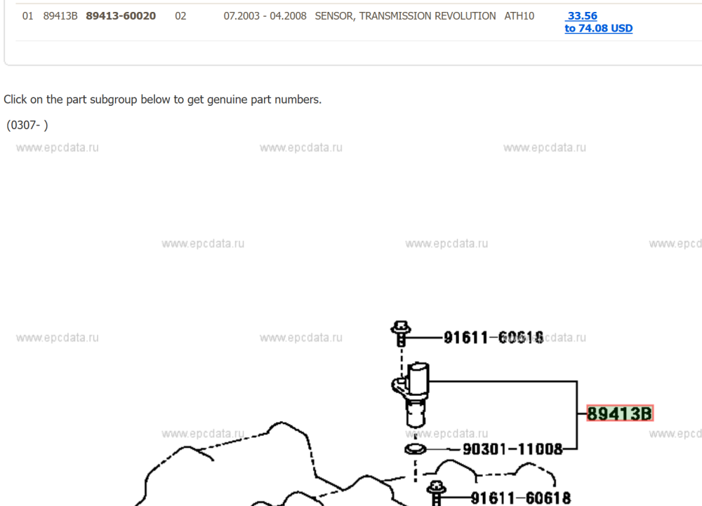
Yes, unfortunately. Secondary pulley rotation speed sensor that detects the output shaft rotation speed is placed on the secondary pulley shaft (reduction drive gear), which is NOUT. This the top one on the diagram to the rear of the square shape bit of the gearbox. rab0711c.pdf
-
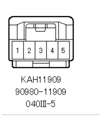
DTC P0500 is a vehicle speed fault, not a gearbox speed sensor issue. Gearbox speed sensor faults are DTC P1820 and P1825. The speed signal comes from the wheel speed sensors to the skid control computer then to the combination meter, from there is a wire to the engine ECU, head unit, power amplifier and cruise control. Possibly in that line also is a chip to convert kph to mph. As the issue occured after installing your new head unit I would look at the speed signal wire to that. Grey connector, pin 3, violet colour
-
What about the cruise control you fitted, has that done something to the speed signal?


