


Jeza
Members
-
Joined
-
Last visited
Everything posted by Jeza
-
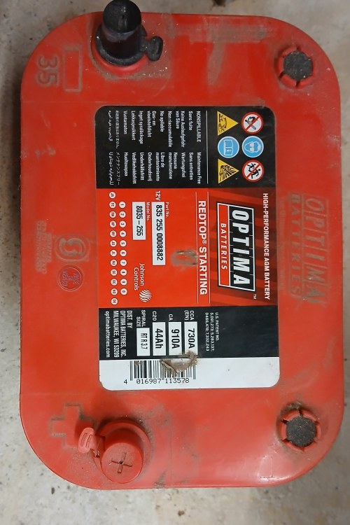
Under the passenger seat on a hybrid is the battery cooling fan, relays, battery ECU and one end of the hybrid battery assy. The aux 12v battery on mine is under the drivers seat the original fitted by CampervanCo was a Optima Red Top Starting only 44Ah 730A which was a mystery to me because the Hybrid does not need a high Ampage battery as the hybrid battery starts the engine, but it does need a high capacity. I managed to squeeze in a slightly larger battery Exide AGM 62Ah, 680A part number EK620. L02 size 242 x 175 x 190. There is quite a high drain on the battery when parked up for any length of time from various ecu's alarm radio central locking, and once the battery has been discharged it won't be able to supply enough power for the hybrid ecu to start the engine. on turning on the ignition I have found the voltage can drop by nearly 2 v.
-
Who did your conversion?
-
Wiring diagrams attached hdam3860.pdf hdam3810.pdf hdam3820.pdf hdam3830.pdf hdam3840.pdf hdam3850.pdf
-
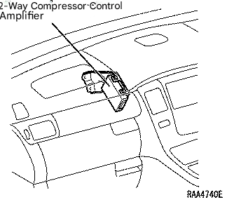
I have another picture for the location of the 2-way compressor control amplifier and it is to the side of the blower, possibly get access by removing the two passenger storage bins and the trim panel. From the manual, which I have nearly finished translating, It outputs a compressor drive signal to the A/C inverter according to the operation enable signal from the HV control computer and the signal from the dual automatic air conditioning computer. In addition, when belt drive is used, it inputs a variable capacity signal from the dual automatic air conditioning computer to control the compressor control valve. The computer is built into the control panel. There is a self test that can be performed on the panel; While simultaneously pressing the "AUTO" switch and the "Inside/Outside Air Change" switch on the control panel, change the IG switch from the OFF position to the engine start position. When panel diagnosis is activated, an indicator check is performed automatically. Check that all indicators and setting display sections light up and go out four times at 1 second intervals. Once the indicator check is complete, a sensor check will be performed automatically. Press the “inside/outside air change” switch to perform an actuator check. After the actuator check is completed, press the “AUTO” switch to perform a sensor check again. The result of the sensor check is displayed on the set temperature display. To end the panel diagnosis, press the “OFF” switch. [Electronic Technical Manual] AC fault codes.pdf
-
-
Hi, is the 12v battery good? monitor the voltage when the ignition is turned on if it drops below 10-11 v this will affect the ECU's, they won't play. The HV battery cells are all connected in series so only as good as the weakest cell, just like a chain. If there was a problem with block 10 you would get code P3020 P3004 depends on what the sub code is: -131 When the EV battery fuse is blown, the service plug grip is dislodged, or the high voltage wiring resistance is broken. -132 Inverter voltage sensor abnormality or high voltage wiring resistance increase -133 Abnormal signal received from battery computer ASSY -268 Inverter voltage signal is out of sync with HV battery voltage
-
Are you sure it is P1325 as inverter faults are P3123-xxx, if so, you need to find the sub code (-xxx) to identify the part in the inverter or wiring to the ECU's.
-
Because of its small capacity of 44Ah, it is important to keep it charged up if not regularly using the vehicle, at least once a week. I plug in the AC hook up every week ,with a dehumidifier running inside as well when not using the van after the roads have been gritted or a foot of snow as we have now.
-
Check with your conversion company to see what battery they installed. It has to be low enough to clear the underside of the seat, I guess it is raised up slightly with a swivel base. If it is a CampervanCo conversion they installed a Red top AGM battery in mine.
-
You don't need to power down the HV to clean the Hybrid ECU. From the description of what is happening and the lights it looks like a HV battery issue, one bad block is all it takes. If the capacity of the block reduces, it will charge up quicker then discharges quicker than the rest. You also have a HV battery temp warning on and a motor generator temp warning on as well, is the HV battery cooling fan on max. Check behind the front passenger seat forward trim in the footwell for water, the HV battery ECU connector is there. You need to get a code reader to find out what is going on.
-
Finger trouble!! just replace the bad pair of cells. A few hybrid battery repair companies around that can test and repair your battery.
-
Hi, I presume it is, a better performing with smarter charging than the gen 2. You have to replace all the modules within the battery. The battery is only as good as the weakest cell, so you could
-
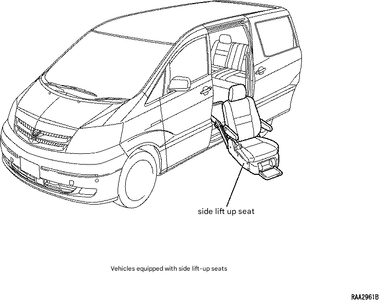
A power seat mechanism and side lift-up mechanism are available on the left side of the captain's seat as a manufacturer option. Approx dimensions; Ground to floor - 52cm Rear door lower opening trim to top of rear opening - 120cm As Rojie has already mentioned the tail gate hangs down a bit when open
-
If you are removing the engine ECU to clean the contacts and harness connectors, the hybrid ECU is the box forward and at right angles to it. While you are in there, it would be worth cleaning those contacts /connectors as well.
-
They are on facebook which gives you some idea of the different work they do plus reviews.
-
Try AME vehicle service & repair - Insch aberdeenshire. I use them for my 2003 hybrid great service, I am about to get them to change the rear trailing arm bushes, I usually provide the parts.
-
If the 12v battery, most likely the engine ECU relearning the idle settings after battery disconnection. Also you will find the drivers door window controls for the other doors won't work, you need to lower and raise each window by its own door switch first.
-
Initial engine start by turning the key uses the Hybrid motor in the gearbox. Subsequent engine starts uses the starter/generator driving the toothed serpentine belt on the front of the engine. Check the belt first, also the tensioner, water pump, aircon pump, idler pulley and crankshaft pulley which are all connected to the belt.
-
I have an ICarsoft reader for the early toyota, 2003 hybrid, and techstream. Techstream gives far more info and is easier to read live data. However I find if the Hybrid system has gone into safe mode, or worse, neither can communicate with the ECU. The early models communicate through the OBD port on the J line to the engine ECU, the canbus is very limited.
-
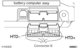
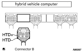
C1213 - The skid control computer communicates with the hybrid control computer and controls the braking force in coordination with the motor regenerative operation. Reception or transmission to or from the hybrid control computer is not possible. Check the sub code on the data page, could be 152, 153 or 154. This is not necessary a fault, if there is an issue with the hybrid system it stops talking to the other systems. P1636/81 When communication from the Engine Control Computer with the hybrid vehicle control computer is lost Possible issues - Wire Harness or Connector or computers P3002 - When an error occurs in communication from the hybrid vehicle computer to the battery computer ASSY Wire Harness or Connector Hybrid Vehicle Computer Battery computer assembly As the hybrid computer seems to be the common issue I would check all the connectors and harnesses on both the ECU, hybrid computer and battery ECU for damage and water ingress. ECU's are located behind the passenger stowage box and the battery ECU under the passenger seat, connector accessible behind forward trim. I can give you the connectors and relevant pins to check for continuity of each harness. Interestingly on P3002 fault diagnosis the first check is to "Stop operation of all aftermarket vehicle products or electrical products brought into the vehicle." then check if the fault code reappears. attached images are for P3002.
-
If the light comes on, when you stop check for codes before turning the engine off.
-
The inverter/converter is very well sealed as is the battery. I would look at this as two separate issues to start with. Do you get any warning lights come on? Is the 12v aux battery good, full capacity and holding charge? When trying to start can you hear the Hybrid relays click from under the passenger seat? Have you checked for any jobd fault codes? Low power could be the engine or the Hybrid system sensing an issue and going into safe or limp mode, engine revs more especially at low speeds. I presume the water leak clear water and not coolant!
-
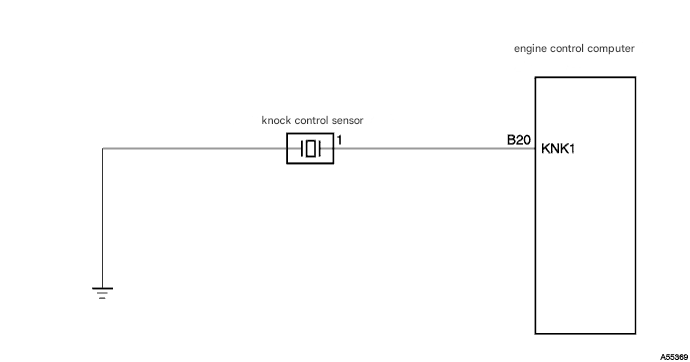
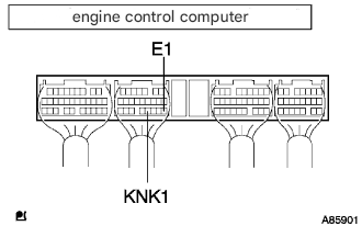
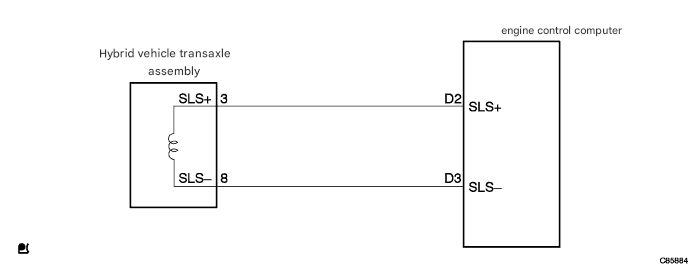
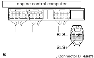
Knock sensor P0325/52 - When the knock control sensor is disconnected or shorted for 10 seconds or more at an engine speed of 2000 to 4500 rpm after the engine has warmed up. Possible issues; Wire Harness or Connector - ECU connector B, kah11476 pin 20 Knock Control Sensor - this is hidden under the inlet manifold, I read somewhere that it is possible to access it from going in from under the engine!! Knock control sensor not tightened properly Engine Control Computer check the continuity between the engine control computer's vehicle side connector B20 (KNK1) terminal and the body earth. standard: No continuity 1885/77 - When the hydraulic pressure command value is 0.5 MPa or less and the sensor output value is 3.0 MPa or more for 3 seconds or more. Wire Harness or Connector Hybrid vehicle transaxle assembly Engine Control Computer Disconnect connector D of the engine control computer. check the resistance between the engine control computer's vehicle side connector D2 (SLS+) terminal and D3 (SLS-) terminal. kah11638 Reference value: 5.0-5.6 ohms. I would remove all the ECU connectors, spray with electrical contact cleaner, check for damage, corrosion and damage to the harnesses. Also check in the gearbox area for any damaged wiring and check connectors ar seated correctly.

-
This is a connector on the head unit that feeds in the vehicle speed. Note this is for a 2.4 10 series hybrid , your wiring will probably be different.
-
Thanks, but I have adapted a script from another menu .html file and now the wiring menu works. Sounds a bit dodgy buying from a Russian in crypto 🤔


